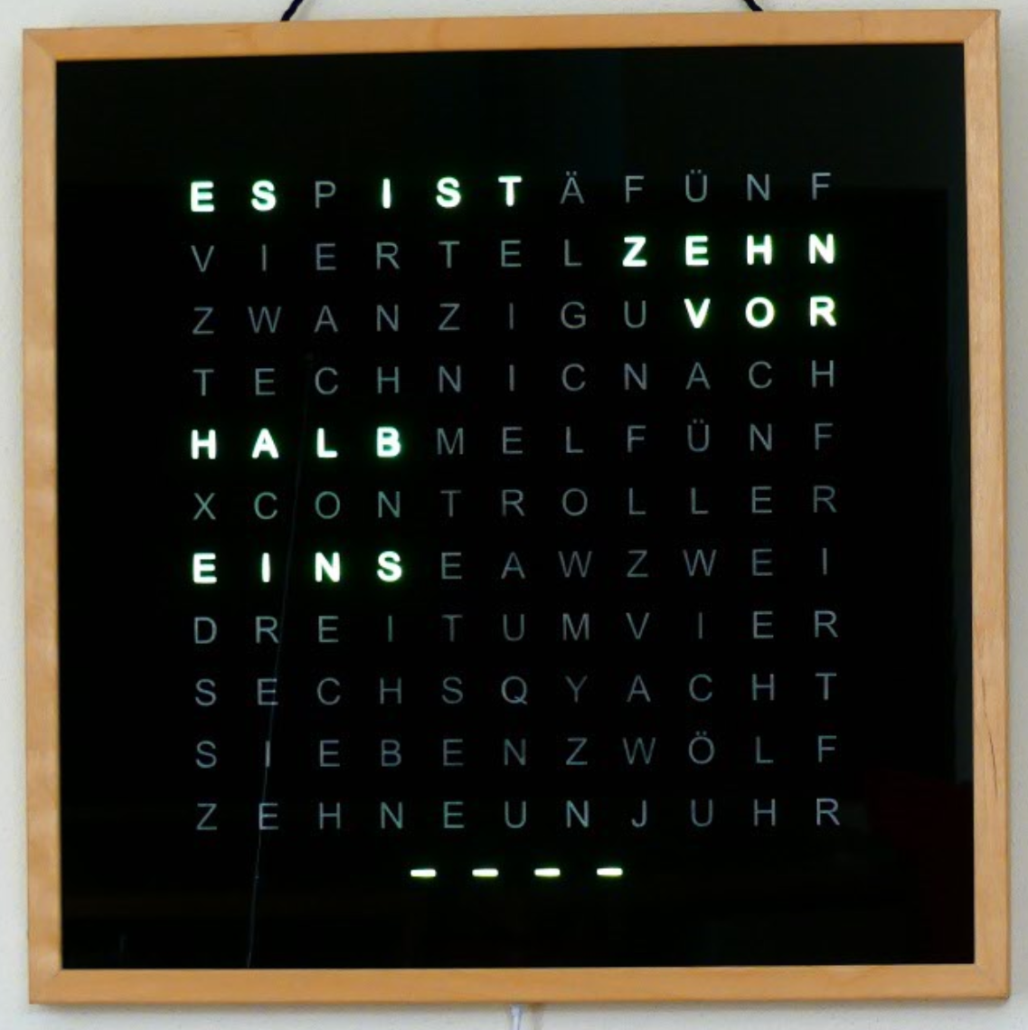
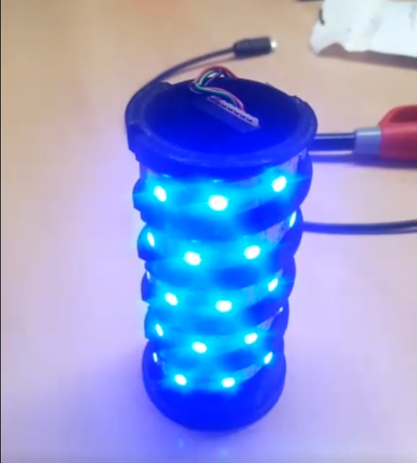
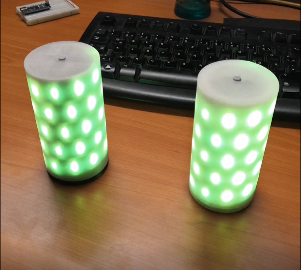
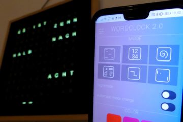
In this article, I present my basic hardware and software parts for a smart LED lamp project, which is to be controlled via WiFi. Two examples of such a project are a decoration LED tube light and my newest word clock, which requests the time via the Internet and displays it by means of an LED matrix.
Hardware
First, I would like to introduce the main electrical components for such a smart led lamp.
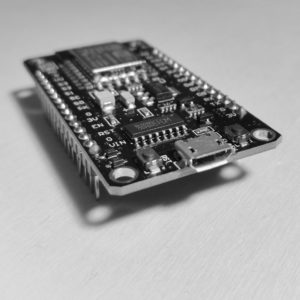
Microcontroller with WLAN interface
I recommend here, for example, the inexpensive ESP8266, which will be known to one or the other Maker. This microcontroller can be programmed very comfortably, like an Arduino, with the Arduino IDE, but in contrast to a traditional Arduino, it has a WLAN interface, with which you can connect to a WLAN network very easily. The large flash memory of the ESP8266 also makes it possible to host a small website, which can be used as a user interface. If you search online for ESP8266, you will find many designs of the ESP8266. I recommend for beginners especially the boards which already have a USB port for programming, for example, the so-called NodeMCU board.
LEDs
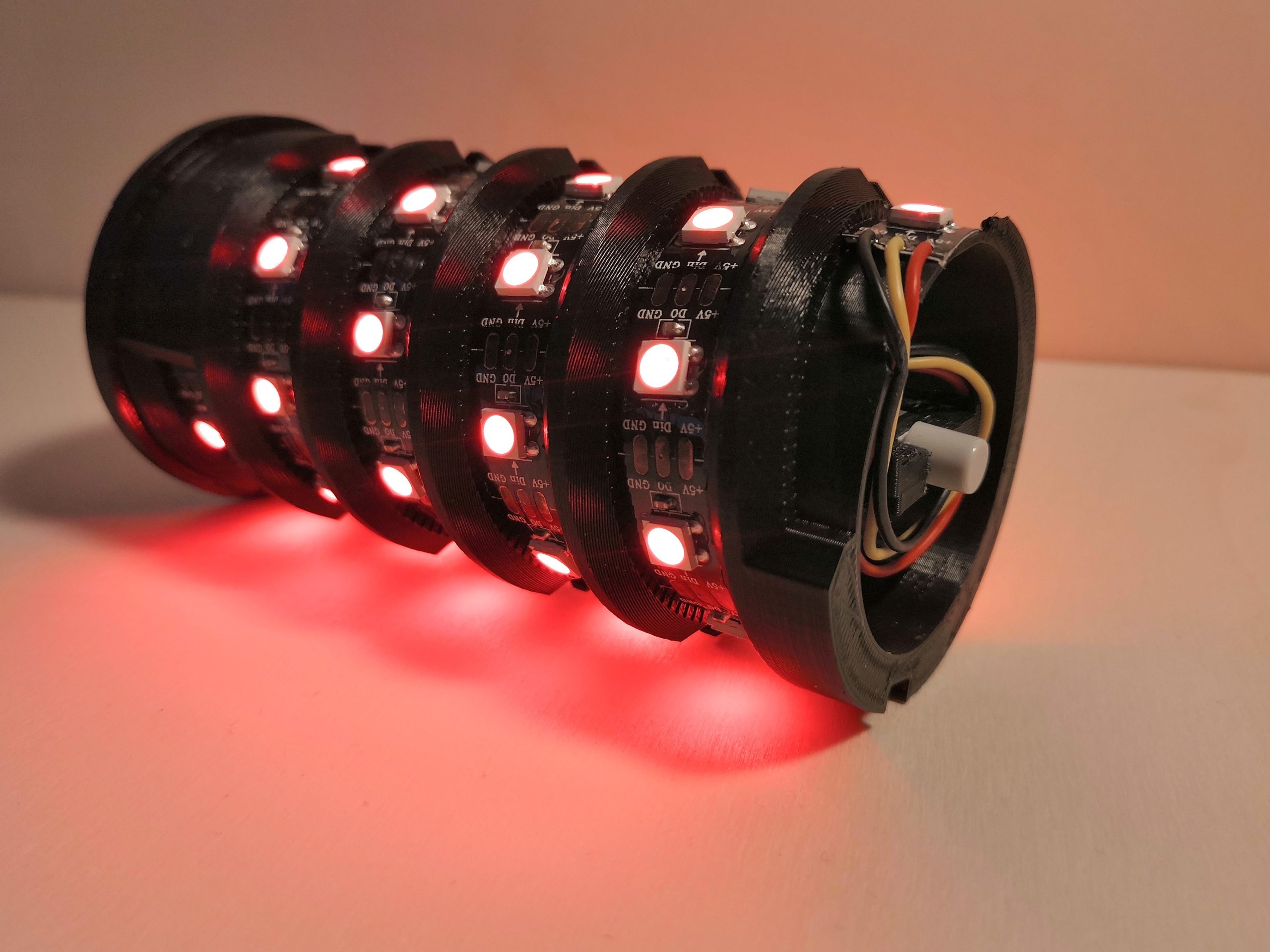
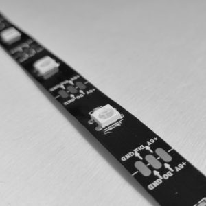
The most important component for a smart lamp is of course the LEDs. The busable NeoPixel RGB LEDs with the official designation WS2812b are very popular among makers worldwide. Busable in this context means that any number of LEDs (max. 1024) can be controlled individually via a data line serially one after the other. Each NeoPixel LED has four pins: One pin for data input (DI), one pin for data output (DO), which leads to the next LED, and two pins for power supply (5V) and ground (GND). You can buy the LEDs for example as LED strips or already as ready-made LED matrices in different sizes. A ready-to-use library for Arduino allows controlling the LEDs with fewer lines of code.
Power supply
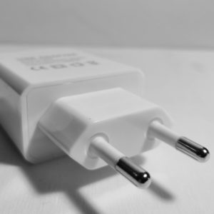
The power supply is an issue that should not be neglected in these projects. Each NeoPixel LED requires about 20mA for each color (red, green and blue) at a supply voltage of 5V. So in total, you have to calculate a current requirement for the LEDs of 60mA. For a matrix of 10×10 LEDs, this results in a maximum current consumption of 6A! This is where a classic USB power supply, like the one you know from your smartphone, reaches its limits.
Of course, you probably won’t let all the LEDs glow white at full brightness and so you can make some compromises, just don’t be surprised if the LEDs turn off all of a sudden because the voltage of the power supply drops. The ESP8266 needs some 100mA for the startup, so also here a sufficient power supply is to be paid attention to. For the boards, which already have a USB connection, one does not have to worry so much since here the supply comes directly over USB. For the NeoPixel LEDs, you can tap the 5V USB voltage before the board (do not let the current of the LEDs run over the board, otherwise damage can occur).
Electronics trivia and circuit diagram
Besides the main components, you need a few small things to start the first run. First, the developer of the NeoPixel LEDs recommends a 1000μF electrolytic capacitor between the supply lines and second, a 470 Ohm resistor in the data line before the first LED in the row. The finished circuit should look something like this:
That was the hardware setup. Now, we can turn to the software.
Software
I have published an example project for the smart LED lamp on GitHub, which already contains all the points mentioned below and can serve as a basis for your own developments. I would like to give a few hints here, which should not be missing in such a project.
Integrated Development Environment (IDE)
The free Arduino IDE is perfectly suited for programming the ESP8266. If you also want to make use of syntax completion, I can also recommend Visual Studio Code with the Arduino extension. However, with both development environments, the ESP8266 is not available as a board by default and must be installed afterwards. More information about this I already described in the following post:
Libraries
As mentioned above, there are ready-made libraries for the NeoPixel LEDs. The most important one is Adafruit_NeoPixel (or Adafruit_NeoMatrix for LED matrices), which can be easily installed via the Arduino IDE. For the use of the ESP8266, some standard installed libraries are necessary, which I don’t list here. You can find them in the example project on GitHub.
OTA update
From my point of view, the most important SW feature is the OTA update capability. That means the possibility to update the program via WiFi to the ESP8266. There are many tutorials online on how to implement this. The sample code above already has the feature implemented and believe me, it will make your life incredibly easier.
Web server and file system
Also, the setup of the above-mentioned file system and webserver, with which you can store and host your own files on the ESP8266, is from my point of view an absolute must. This allows you to design your own user interface with HTML/JavaScript and CSS and pass commands from the user interface directly to the ESP8266 program using GET/POST requests. The sample project includes a simple website, which can be used to change the color of the LED strip.
To use the file system and the webserver even more efficiently I recommend the instructions and sample codes from here. There are two possible filesystems for ESP8266 possible: SPIFFS and LittleFS. The difference is mainly that LittleFS supports also folders instead of just files and it is a little bit faster than SPIFFS. But the downside is, that LittleFS uses some more overhead memory per file which can be a problem if you have just an ESP8266 version with less memory.
Access point mode as fallback (setup)
In normal operating mode, the ESP8266 is integrated as a client in a WiFi network. This makes sense because you can access the webserver from all devices in the network. But if you want to take the lamp to another location and the set network is not available, I recommend the implementation of a fallback mode, in which the ESP8266 provides its own WLAN hotspot to setup the login data for the new WiFi network. There is a very neat Library called WiFiManger, which handles the whole WiFi setup. So there is no need to implement this fallback mode yourself.
I think now nothing stands in the way of your own project with smart LEDs. Have fun with the
implementation!


0 Comments